A small change to the default
The energy retrofit could have used a standard panel layout. The proposal kept the same system but gave the facade a more deliberate rhythm.
Work
Revit and Dynamo workflow for a facade retrofit in Nus, using 20, 30, and 40 cm panels to create an editable pattern and clear construction drawings.
Stage
For an industrial building in Nus, a Revit and Dynamo workflow arranged 20, 30, and 40 cm panels into an editable pattern and a clear drawing set.
The energy retrofit could have used a standard panel layout. The proposal kept the same system but gave the facade a more deliberate rhythm.
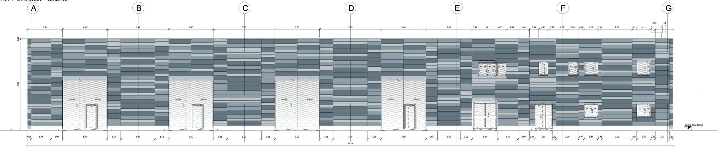
The pattern uses 20, 30, and 40 cm panels around the existing windows, doors, and facade breaks.
Dynamo generated the arrangement while Revit families carried the dimensions, materials, details, and drawing information.
Color-coded elevations made each panel width easy to distinguish while keeping dimensions and openings visible.
Backstage
I turned a visual idea into a few practical rules, then used Dynamo to handle the repetition while Revit kept the model and drawings together.
I used windows, doors, and facade breaks to divide the elevation into fields before generating any panels.
I kept the system to 20, 30, and 40 cm widths, which gave the pattern variation without inventing new panel types.
The graph shuffled the available widths, placed the families, and wrote their dimensions and materials back into Revit.
I used color to separate the panel widths so the generated pattern could be checked and understood in the drawing set.